INSTALLATION
Step 1
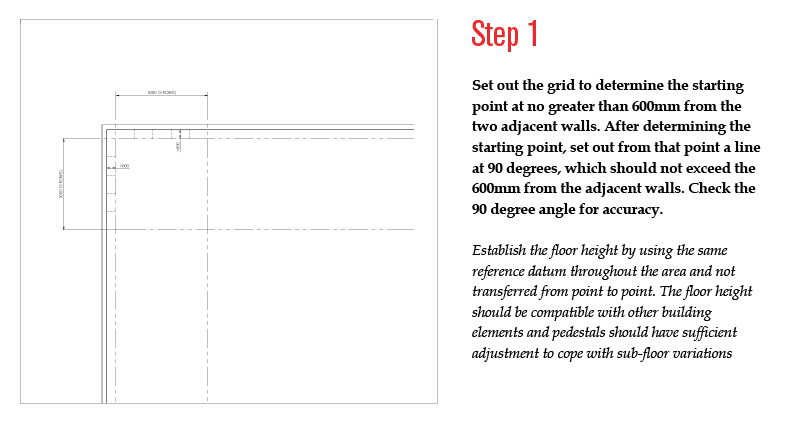
Set out the grid to determine the starting point at no greater than 600mm from the two adjacent walls. After determining the starting point, set out from that point a line at 90 degrees, which should not exceed the 600mm from the adjacent walls. Check the 90 degree angle for accuracy.
Establish the floor height by using the same reference datum throughout the area and not transferred from point to point. The floor height should be compatible with other building elements and pedestals should have sufficient adjustment to cope with sub-floor variations.
Step 2
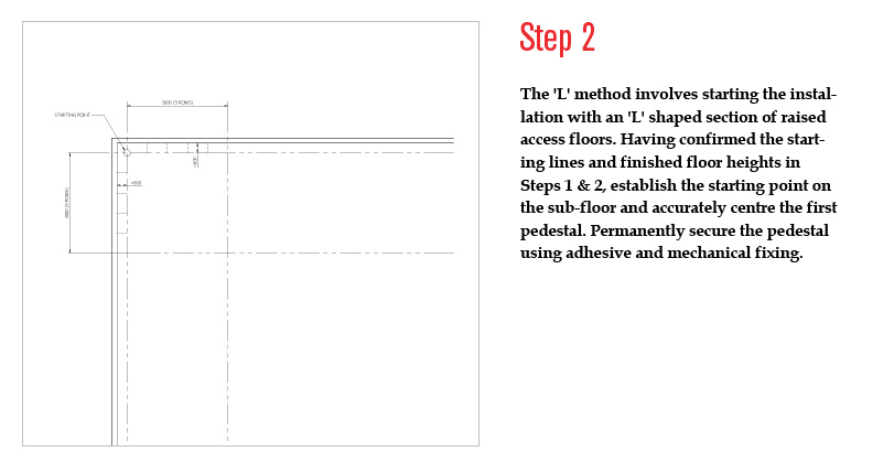
The 'L' method involves starting the installation with an 'L' shaped section of raised access floors. Having confirmed the starting lines and finished floor heights in Steps 1 & 2, establish the starting point on the sub-floor and accurately centre the first pedestal. Permanently secure the pedestal using adhesive and mechanical fixing.
Step 3
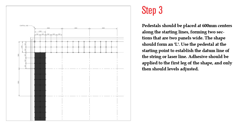
Pedestals should be placed at 600mm centers along the starting lines, forming two sections that are two panels wide. The shape should form an 'L'. Use the pedestal at the starting point to establish the datum line of the string or laser line. Adhesive should be applied to the first leg of the shape, and only then should levels adjusted.
Step 4
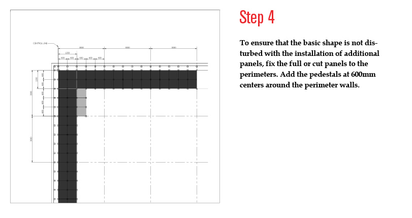
To ensure that the basic shape is not disturbed with the installation of additional panels, fix the full or cut panels to the perimeters. Add the pedestals at 600mm centers around the perimeter walls.
Step 5
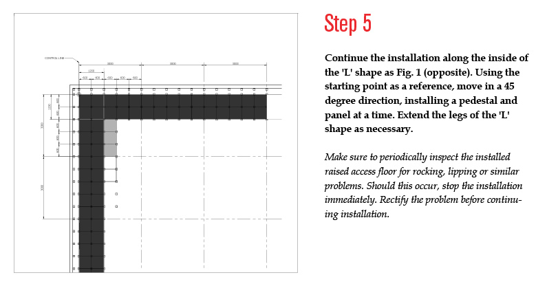
Continue the installation along the inside of the 'L' shape as Fig. 1 (opposite). Using the starting point as a reference, move in a 45 degree direction, installing a pedestal and panel at a time. Extend the legs of the 'L' shape as necessary
Make sure to periodically inspect the installed raised access floor for rocking, lipping or similar problems. Should this occur, stop the installation immediately. Rectify the problem before continuing installation.